Contents
Next: The Brain
Chapter 1:
This is the top level structure in the simulator. This will contain some values to define the simulation as a whole such as the amount of time being simulated and random seed.
During input, the Brain Section will also provide a preliminary outline of other structures to be used in the simulation. The overall structure of the input file is to describe different aspects within the brain as blocks of text. The NCS parser recognizes keywords and creates structures within the model as defined within the blocks. These keywords and their associated parameters are described in the user documentation located on brain.unr.edu/ncsDocs/ncsUser/TOC.html
The order of the blocks is not important as long as the blocks are complete.
Also, the input file can be split up into several files and included using the INCLUDE keyword. The only restriction is that the INCLUDE statement be located outside of any block structure.
The maximum number of characters allowed within a string value is currently 128 characters. Numbers are transformed into their appropriate type, float, double, etc.
| Keyword | Value | Description |
| BRAIN | | REQUIRED: Indicates the start of a Brain definition block. |
| TYPE | | REQUIRED: The name of this Brain configuration. Currently used by the Server program (port-based IO) to create and manage the ports. |
| JOB | | REQUIRED: Job Name
Any files generated during the simulation will be given the JOB string as a prefix followed by a period or a dash (depending on the version of NCS used) then whatever the filename is to be called (ex. myJob.report1 or myJob-report1 )
By default JOB is the string "job". |
| DURATION | | REQUIRED: Duration of the simulation in seconds.
The amount of time, in seconds, which will be simulated.
This value is multiplied by the FSV to determine the number of timesteps for the simulation. |
| FSV | | REQUIRED: FSV = Frequency of Sampling Value
Default value is 1
Typical Value is 10,000
This scales DURATION to set the number of DoThink loop timesteps the simulation will run.
(ex. DURATION = 1.8, FSV = 10000, timesteps = 1.8*10000 = 18000 ) |
| INTERACTIVE | | Currently not implemented |
| SEED | | Random Number Generator Seed Value
This value should be a negative integer. (ex. -999) This sets the seed to be used by the brain's random number generator. This seed is used for the connectivity wthin the brain block as well as the connections between layers and within layers
Note: This SEED value is not responsible for other areas that utilize their own seeds. (ex. COMPARTMENT, CHANNEL, SYNAPSE, SYN_FACIL_DEPRESS, LEARNING (hebbian)
SYN_DATA(deprecated),
STIMULUS) |
| DISTANCE | | Distance Toggle
Flag to indicate that cells should be assigned specific coordinates so that synaptic delays can be calculated based on distance between the source and destination cells. Set to NO by default.
This value must be YES if you want to set OUTPUT_CELLS, OUTPUT_CONNECT_MAP to YES or use the Decay Step Value within a CONNECT statement |
| COLUMN_TYPE | | Column Creation
Alerts the simulator to expect a column(s) to be defined with the name given. If a column is defined without being listed in the Brain section, that column will be ignored and not generated in the resulting brain model structure.
Can have multiple values listed. |
| STIMULUS_INJECT | | Stimulus Injection Creation
Alerts the simulator to expect a stimulus to be defined with the name given. If a stimulus is defined without being listed in the Brain section, that stimulus will be ignored and not generated in the resulting brain model structure.
Can have multiple values listed. |
| REPORT | | Report Creation
Alerts the simulator to expect a report to be defined with the name given. If a report is defined without being listed in the Brain section, that report will be ignored and not generated in the resulting brain model structure.
Can have multiple values listed. |
| CONNECT | | Column | (string) | | Layer | (string) | | CellType | (string) | | Compartment | (string) | | Column | (string) | | Layer | (string) | | CellType | (string) | | Compartment | (string) | | SynpaseType | (string) | | Probability | (real) | | Speed | (real) |
| Intercolumn Connection Creation
Synapse connections between Columns. Signifies that synapse connections of the type specified should be made from the source (the first four parameters) to the destination (the next four params).
SynapseType is the Type value from the SYNAPSE block of the desired synapse to be used in this connection.
Probability determines how many connections are made randomly.
The speed indicates how quickly the destination cell will receive a signal from the source cell in millimeters per millisecond (mm/ms).
Can have multiple values listed. |
| CONNECT | | Column | (string) | | Layer | (string) | | CellType | (string) | | Compartment | (string) | | Column | (string) | | Layer | (string) | | CellType | (string) | | Compartment | (string) | | SynpaseType | (string) | | Probability | (real) | | Decay_Step | (real) | | Speed | (real) |
| Intercolumn Connection Creation with Decaying Distance Effects
Definitions are the same as above with the following exception:
If DISTANCE is set to YES, then connections are made based on a decaying probability based on distance.
The probability is at its maximum (the value given) if there is no distance between the source and destination cell. As the distance increases by the Decay Step, the probability exponentially decays.
If DISTANCE is set to NO, then probability is used as a constant for all connections and the Decay Step value is ignored. |
| RECURRENT_CONNECT | | ColumnA | (string) | | LayerA | (string) | | CellTypeA | (string) | | CompartmentA | (string) | | ColumnB | (string) | | LayerB | (string) | | CellTypeB | (string) | | CompartmentB | (string) | | SynpaseType | (string) | | ProbabilityAtoB | (real) | | ProbabilityBtoA | (real) |
| Establishes that two previous CONNECT statments are recurrent with each other. This means that as the two cell groups are connected, a minimum percentage of cells have both forward connections and reverse connections. The first group listed (Column, Layer, Cell, Cmp) is designated group A while the second group (Column, Layer, Cell, Cmp) is designated group B. The previous CONNECT statements need to use these two groups with A connecting to B in one, and B connecting to A in another (order of appearance does not matter). Both these CONNECT statements must use the specified synapse. The Probability values indicate that a minimum percentage of connections made must be recurrent. For example, if ProbabilityAtoB is 0.5, then 50% of the cells with connections from A to B will also have a returning connection from the same cells in B to A. |
| SAVE | | filename | (string) | | value | (real) |
| Brain State Save
Specifies that the brain simulation should save the entire current state to the file name specified at the time (seconds) given. The file will save by default to your current working directory unless a full path is specified. |
| LOAD | | Brain State Load File
A brain saved in the file specified will be restored to run with new stimulus and reports. The file will load by default from your current working directory unless a full path is specified. |
| OPTION | | Disables simple warning messages. Warnings are on by default |
| OUTPUT_CELLS | | Output Cell Locations
Flag to indicate that cell positions should be output to the file job.cells.dat in the current working directory.
See NCS Cell Coordinate Output for more details.
Set to NO by default. |
| OUTPUT_CONNECT_MAP | | Output Synapse Locations
Flag to indicate that synaptic connections should be output to the file job.synapse.dat in the current working directory.
See NCS Connect Map Output for more details.
Set to NO by default. |
| END_BRAIN | | REQUIRED: Indicates the end of a Brain definition section. |
Example
The following BRAIN block would create a 3-column brain with two different stimulii.  There are two intercolumn connections.
It would output two different reports. Distance and output is off for this run.
BRAIN
    TYPE               Brain1Col
    JOB                BinRep
    DURATION           1.8
    FSV                10000
    INTERACTIVE        NO
    SEED               -999
    DISTANCE           NO

    COLUMN_TYPE        AI1
    COLUMN_TYPE        AI2
    COLUMN_TYPE        ASSC1

    STIMULUS_INJECT    StimInject_AI3
    STIMULUS_INJECT    StimInject_AI1Clear

    REPORT             AI1_Lay3_Exc-cNAC_1
    REPORT             AI1_Lay4_Exc-cNAC_1

    CONNECT            AI1    Lay3    Exc-cNAC    s1
                       AI2    Lay3    Inh-cNAC    s1
                       ExcF2Hebb0	    0.05        3
    CONNECT            AI2    Lay3    Exc-cNAC    s1
                       AI1    Lay3    Inh-cNAC    s1
                       ExcF2Hebb0     0.05        3

    SAVE               Brain1Col.sav  1.0
    OUTPUT_CELLS       NO
    OUTPUT_CONNECT_MAP NO
END_BRAIN
RECURRENT_CONNECT Examples
1. Recurrent connects between a single cell group E1, declared in a BRAIN section.
	CONNECT
				R2A_AI_1	layer_R2	E1	sE1
				R2A_AI_1	layer_R2	E1	sE1
				ExcitSyn1_Intra_E1	0.12	0
	RECURRENT_CONNECT
				R2A_AI_1	layer_R2	E1	sE1
				R2A_AI_1	layer_R2	E1	sE1
				ExcitSyn1_Intra_E1	1.0	0

This can also be declared in COLUMN and LAYER sections. The difference would be the way we specify source and destination cell groups.
In COULMN section, specify Layer, CellType and Compartment. In case of LAYER section, just specify CellType and Compartment.

2. Recurrent connects between two cell groups E1 and E2, declared in a BRAIN section.
	CONNECT
				R2A_AI_1	layer_R2	E1	sE1
				R2A_AI_1	layer_R2	E2	sE2
				ExcitSyn1_Inter	0.04	0
	CONNECT
				R2A_AI_1	layer_R2	E2	sE2
				R2A_AI_1	layer_R2	E1	sE1
				ExcitSyn1_Inter	0.04	0
	RECURRENT_CONNECT
				R2A_AI_1	layer_R2	E1	sE1
				R2A_AI_1	layer_R2	E2	sE2
				ExcitSyn1_Inter	1.0	1.0

As in previous example, this can also be declared in COLUMN and LAYER sections with same difference.
Chapter 2:
Columns form a container for the Layers
Column Shells
| Keyword | Value | Description |
| COLUMN_SHELL | | Indicates the start of a Column Shell definition area |
| TYPE | | The name which is used to refer to this object |
| WIDTH | | The width (or radius) of the column (units?) |
| HEIGHT | | The height of the column (units?) |
| LOCATION | | The x, y coordinates of the column |
| END_COLUMN_SHELL | | Indicates the end of a column shell definition section |
Example
COLUMN_SHELL
        TYPE                    VIshell
        WIDTH                   300
        HEIGHT                  800
        LOCATION                0               800
END_COLUMN_SHELL
Fill Columns
| Keyword | Value | Description |
| COLUMN | | Indicates the start of a Column fill section |
| TYPE | | The name which will be used to refer to this object |
| COLUMN_SHELL | | The name of the column shell which this column will use |
| LAYER_TYPE | | The name of a layer which will be present in this column |
| CONNECT | | Layer | (string) | | CellType | (string) | | Compartment | (string) | | Layer | (string) | | CellType | (string) | | Compartment | (string) | | SynapseType | (string) | | Probability | (real) | | Speed | (real) |
| Synapse connections between Layers. Synapse connections of the type specified are formed from the source Layer, CellType, Compartment (first set) to the destination Layer, CellType, Compartment (second set). Connections are made randomly with the probability specified. The speed indicates how quickly the destination cell will receive a signal from the source cell (units?). |
| END_COLUMN | | Indicates the end of a Column fill section |
Example
COLUMN
	TYPE			AI1
	COLUMN_SHELL		AIshell
	LAYER_TYPE		Lay3
	LAYER_TYPE		Lay4
	CONNECT
                                Lay4		Exc-cNAC	s1
                                Lay3		Exc-cNAC	s1
                                ExcF2Hebb0	0.1		3
END_COLUMN
Chapter 3:
Layers form a container object for cells
Layer Shells
| Keyword | Value | Description |
| LAYER_SHELL | | Indicates the start of a layer shell definition section |
| TYPE | | The name which will be used to refer to this layer shell |
| LOWER | | Layers are placed in columns based on percentages. The LOWER value represents where on the Column this Layer will begin. Ex. A value of 35 means that the Layer will begin at .35*the Column's height |
| UPPER | | Layers are placed in columns based on percentages. The UPPER value represents where on the Column this Layer will end. Ex. A value of 35 means that the Layer will end at .35*the Column's height. |
| END_LAYER_SHELL | | Indicates the End of a layer shell definition section |
Example
LAYER_SHELL
        TYPE                    layer_shell_A
        LOWER                   0
        UPPER                   35
END_LAYER_SHELL
Fill Layers
| Keyword | Value | Description |
| LAYER | | Indicates the start of a fill layer section |
| TYPE | | The name which will be used to refer to this layer |
| LAYER_SHELL | | The name of the layer shell which will be used by this layer |
| CELL_TYPE | | celltype | (string) | | quantity | (integer) |
| This layer is to be filled with cells of the type given and the quantity specified. More than one CELL_TYPE line can be used to put different cell types in a layer. |
| CONNECT | | celltype | (string) | | compartment | (string) | | celltype | (string) | | compartment | (string) | | synapse | (string) | | probability | (real) | | speed | (integer) |
| Synapse connections within a Layer. The source (first two) connects to the destination (second two) with the synapse type specified. Connections are made randomly with the probability specified. The speed indicates how quickly the destination will receive the signal from the source. |
| END_LAYER | | Indicates the end of a fill layer section |
Example
LAYER
        TYPE                    layer_A
        LAYER_SHELL             layer_shell_A
        CELL_TYPE               Excitatory      1000
        CELL_TYPE               Inhibitory      250
        CONNECT
                                Excitatory      s1
                                Excitatory      s1
                                ExcitF2Hebb0    0.1             3
        CONNECT
                                Excitatory      s1
                                Inhibitory      s1
                                ExcitF2Hebb0    0.1             3
        CONNECT
                                Inhibitory      s1
                                Excitatory      s1
                                InhibF1Hebb0    0.05            3
        CONNECT
                                Inhibitory      s1
                                Inhibitory      s1
                                InhibF1Hebb0    0.05            3
END_LAYER
Chapter 4:
Cells form a container for the compartments
| Keyword | Value | Description |
| CELL | | Indicates the start of a cell definition section |
| TYPE | | the name which will be used to refer to this Cell type |
| COMPARTMENT | | name | (string) | | label | (string) | | x | (real) | | y | (real) |
| name is a compartment defined in the input file (where the charateristics of that type of compartment are defined), label is a tag that will be used to refer to this compartment when assigning this compartment to other objects such as stimulus, x and y are the relative coordinates of the compartment in the cell. |
| CONNECT | | Compartment | (string) | | Compartment | (string) | | Speed | (integer) | | G | (real) |
| Connections between Compartments. The source (first) connects to the destination (second). The connections have the speed specified. G??? |
| END_CELL | | Indicates the end of a cell definition section |
Example
CELL
        TYPE                    Exc-cNAC
        COMPARTMENT             Soma-cNAC       s1      0       0
END_CELL
Chapter 5:
Activity happens within the Compartments of the Cells.
| Keyword | Value | Description |
| COMPARTMENT | | Indicates the start of a Compartment defintion section |
| TYPE | | The name used to refer to this compartment |
| SEED | | The number used to seed the random nuber generator for the compartment |
| SPIKESHAPE | | The name of the spike shape to use in the compartment when it reaches threshold. |
| SPIKE_HALFWIDTH | | Deprecated. A compartment formerly could only become active if it had a halfwidth along with a spikeshape and threshold. The halfwidth parameter is no longer used by NCS. |
| TAU_MEMBRANE | | This value is used along with R_MEMBRANE to calculate the capacitance of the compartment.
( Capacitance = TAU_MEMBRANE / R_MEMBRANE ) |
| R_MEMBRANE | | This value is used along with TAU_MEMBRANE to calculate the capacitance of the compartment.
( Capacitance = TAU_MEMBRANE / R_MEMBRANE )If R_MEMBRANE = 0, then Capacitance is 0.0 |
| THRESHOLD | | When the compartment's membrane voltage reaches the threshold, it begins a spike shape |
| LEAK_REVERSAL | | When a compartment updates its membrane voltage and there is no voltage clamp, a current leak must be calculated
Current Leak = LEAK_CONDUCTANCE * ( previous membrance voltage - LEAK_REVERSAL ) |
| LEAK_CONDUCTANCE | | When a compartment updates its membrane voltage and there is no voltage clamp, a current leak must be calculated
Current Leak = LEAK_CONDUCTANCE * ( previous membrance voltage - LEAK_REVERSAL ) |
| VMREST | | The voltage of a compartment will start at vmrest |
| CA_INTERNAL | | The compartment will start with the initial CA_INTERNAL specified |
| CA_EXTERNAL | | The compartment will start with the initial CA_EXTERNAL specified |
| CA_SPIKE_INCREMENT | | When a compartment reaches threshold, CA_INTERNAL will be increased by the CA_SPIKE_INCREMENT |
| CA_TAU | | Used to calculate the Calcium persistance of the compartment
Calcium persistance = 1.0 - dt / CA_TAU
where dt is related to the value os FSV specified in the Brain
dt = 1 / FSV
if FSV is 0, dt = 0
if CA_TAU is 0, Calcium persistence = 1.0
if Calcium persistence is less than 0 or greater than 1, it will be adjusted to those bounds
Calcium persistance affects the CA_INTERNAL
CA_INTERNAL = calcium persistance * CA_INTERNAL |
| CHANNEL | | The name of a channel which will be used by this compartment |
| END_COMPARTMENT | | Indicates the end of a compartment definition section |
Example
COMPARTMENT
        TYPE                    Soma-cNAC
        SEED                    999999
        SPIKESHAPE              AP_Hoff
        SPIKE_HALFWIDTH         10              0
        TAU_MEMBRANE            0.015           0.0
        R_MEMBRANE              200             0.0
        THRESHOLD               -40             0.0
        LEAK_REVERSAL           0.0             0.0
        LEAK_CONDUCTANCE        0.0             0.0
        VMREST                  -65             0.0
        CA_INTERNAL             5.0             0.0
        CA_EXTERNAL             0.0             0.0
        CA_SPIKE_INCREMENT      100             0.0
        CA_TAU                  0.07            0.0
        CHANNEL			a
END_COMPARTMENT
Chapter 6:
Channels line the cell membrane and influence the cell's behavior. There are many types of channels. So far, three channels from the K+ family have been implemented in NCS. These are the m-channel, the a-channel, and the ahp-channel abbreviated Km, Ka, and Kahp, respectively.
| Keyword | Value | Description |
| CHANNEL | | Starts a channel definition section. The family value given indicates what kind of channel is to be created.
The current available choices are Km, Ka, and Kahp. Each has some exclusive parameters listed in each's subsection.
More families will be added at a later date. |
| TYPE | | The name which this channel will be refered to in the input file |
| M_INITIAL | | The activating (m) value of the channel |
| M_POWER | | When the m value is used, it is raised by the M_POWER
m^M_POWER |
| REVERSAL_POTENTIAL | | Used in calculating a channel's current status.
Its contribution to the equations is determined by Channel type |
| UNITARY_G | | Used in calculating a channel's current status.
Is used as a multiplier for all Channels. |
| STRENGTH | | Used in calculating a channel's current status.
Is used as a multiplier for all Channels. |
| END_CHANNEL | | Indicates the completion of a channel definition section. |
Km channels
M-Channels (Km) have only an activation particle (m). Inhibits its parent cell from reaching threshold.
| Keyword | Value | Description |
| E_HALF_MIN_M | |
| SLOPE_FACTOR_M | |
| TAU_SCALE_FACTOR_M | |
Example
CHANNEL Km
        TYPE                            m
        M_INITIAL                       0.0             0.0
        REVERSAL_POTENTIAL              -80             0
        M_POWER                         1
        E_HALF_MIN_M                    -44
        SLOPE_FACTOR_M                  40 	20	8.8
        TAU_SCALE_FACTOR_M              0.303
        UNITARY_G			5
        STRENGTH                        0.00015
END_CHANNEL
Kahp channels
AHP-Channels or After Hyper Polarization Channels (Kahp) are voltage independant but Calcium dependant.
| Keyword | Value | Description |
| SEED | | The seed to be used to generate random numbers for this channel object |
| CA_SCALE_FACTOR | |
| CA_EXP_FACTOR | |
| CA_HALF_MIN | |
| CA_TAU_SCALE_FACTOR | |
Example
CHANNEL Kahp
        TYPE                            ahp1
        SEED                            999999
        M_INITIAL                       0.0             0.0
        REVERSAL_POTENTIAL              -80             0
        M_POWER                         2
        UNITARY_G			6
        STRENGTH                        0.00015
        CA_SCALE_FACTOR                 0.000125
        CA_EXP_FACTOR                   2
        CA_HALF_MIN                     2.5
        CA_TAU_SCALE_FACTOR             0.01
END_CHANNEL
Ka channels
A-Channels (Ka) help the cell deal with bacground noise. Has both an activation (m) and an inactivation (h) particle.
| Keyword | Value | Description |
| H_INITIAL | |
| H_POWER | |
| E_HALF_MIN_M | |
| E_HALF_MIN_H | |
| SLOPE_FACTOR_M | |
| SLOPE_FACTOR_H | |
| V_TAU_VALUE_M | |
| V_TAU_VOLTAGE_M | |
| V_TAU_VALUE_H | |
| V_TAU_VOLTAGE_H | |
Example
CHANNEL Ka
        TYPE                            a
        M_INITIAL                       0.0             0.0
        H_INITIAL                       1.0             0.0
        REVERSAL_POTENTIAL              -80             0
        M_POWER                         1
        H_POWER                         1
        E_HALF_MIN_M                    11
        E_HALF_MIN_H                    -56
        SLOPE_FACTOR_M                  18
        SLOPE_FACTOR_H                  18
        UNITARY_G			0.12
        STRENGTH                        2.5
        V_TAU_VALUE_M                   0.0002		9999
        V_TAU_VALUE_H                   0.03	0.08	0.13	0.18	0.23
        V_TAU_VOLTAGE_M                 100
        V_TAU_VOLTAGE_H                 -21	-1	10	21
END_CHANNEL
Chapter 7:
Synapses are the connections between other cells and their compartments. When a compartment reaches threshold, it sends signals to all other compartments which it is connected to.
| Keyword | Value | Description |
| SYNAPSE | | Indicates the start of a synapse definition section |
| TYPE | | The name which this synapse will be referred to in this simulation |
| SEED | | The random number generator will be seeded with the value specified. This number must be less than zero ( SEED < 0) |
| SFD_LABEL | | The short term synaptic dynamic (RSE) to be used |
| SYN_PSG | | The synaptic waveform (PSG) to be used |
| LEARN_LABEL | | The long term synaptic dynamic (Learn) to be used |
| HEBB_START | | Time (in seconds) at which Hebbian learning, specified by LEARN_LABEL, will be turned ON for this synapse. By default, Hebbian is ON from start of simulation. |
| HEBB_END | | Time (in seconds) at which Hebbian learning, specified by LEARN_LABEL, will be turned OFF for this synapse. |
| DATA_LABEL | | Deprecated. The synaptic conductance (Data) to be used |
| ABSOLUTE_USE | | The initial value of a Synapse's USE value |
| RSE_INIT | | The initial value of a Synapse's RSE is one (1) by default. This parameter will vary that value between a min and max value. Note that the RSE can only be a value from 0.0 to 1.0. NCS will automatically limit the RSE if it tries to exceed either of those extremes. |
| PREV_SPIKE_RANGE | | Synapses keep track of the time at which a last spike occurred. When a simulation begins, the time will be zero (0) for all Synapses by default. Using this parameter allows a Synapse to vary that previous time within a range from the min to max time (in seconds). |
| MAX_CONDUCT | | Used with SYN_REVERSAL in calculating the current value of a PSG waveform
I(t) = MAX_CONDUCT * CurrentPSGValue * (SYN_REVERSAL - Membrane Voltage) |
| DELAY | | minDelay | (real) | | maxDelay | (real) |
| A created synapse will be given a delay that falls within the range from minDelay to maxDelay. Before a synapse will output a new waveform, it will wait for the DELAY to expire. This value is given in seconds and will be converted using the FSV. If DISTANCE is turned on, this synaptic delay will combine with the traversal delay. |
| SYN_REVERSAL | | Used with MAX_CONDUCT in calculating the current value of a PSG waveform
I(t) = MAX_CONDUCT * CurrentPSGValue * (SYN_REVERSAL - Membrane Voltage) |
| END_SYNAPSE | | Indicates the end of a synapse definition section |
Example
SYNAPSE
        TYPE                    ExcF2Hebb+-
        SEED                    -999999
        SFD_LABEL               F2
        SYN_PSG                 PSGexcit
        LEARN_LABEL             +-HEBB
        MAX_CONDUCT             0.01
        DELAY                   0.0008          0.0012
        SYN_REVERSAL            0               0
        ABSOLUTE_USE            0.32            0.0
        RSE_INIT                0.5             0.8
        PREV_SPIKE_RANGE        0.1             0.1
END_SYNAPSE
Turning Hebbain learning ON and OFF Example
Following is an example of Hebbain learning turned on from 200 msec to 600 msec. Remember, by default Hebbain learning is on, so first turn it off.
SYNAPSE
	TYPE			ExcitSyn1_Intra_E1
	SFD_LABEL		NO_SFD
	LEARN_LABEL		POS_NEG_HEBB
	# Turn off Hebbian initially
	HEBB_END		0
	# Turn on Hebbian from 200 msec to 600 msec
	HEBB_START		0.2
	HEBB_END		0.6
	SYN_PSG			PSGexcit
	MAX_CONDUCT		0.020		0.0
	DELAY			0.001		0.001
	SYN_REVERSAL		0		0
	ABSOLUTE_USE		0.250		0.0
END_SYNAPSE
Chapter 8:
| Keyword | Value | Description |
| SYN_FACIL_DEPRESS | | Indicates the start of a RSE definition section |
| TYPE | | The name which is used to refer to this RSE |
| SEED | | The random number generator for this object will use the seed specified |
| SFD | | The RSE function to use in the synapse. Choices are:
NONE - assumes no RSE is being calcuated
DEPR - assumes depression but no facilitation
FACIL - assumes facilitation but no depression
BOTH - has both facilitation and depression |
| FACIL_TAU | | The initial value of the facilitation tau.
Used in determining how much neuro transmitters are released with each spike |
| DEPR_TAU | | The initial value of the depression time constant.
Used in determining how much neuro transmitters are released with each spike |
| END_SYN_FACIL_DEPRESS | | Indicates the end of a RSE definition section |
Example
SYN_FACIL_DEPRESS
        TYPE                    F1
        SEED                    999999
        SFD                     FACIL
        FACIL_TAU               0.376           0.0
        DEPR_TAU                0.045           0.0
END_SYN_FACIL_DEPRESS
Chapter 9:
Long Term synaptic dynamics or Hebbian learning also determines the effectiveness of a synapse. Depending on when a synapse's pre-synaptic spike occurs, there can be positive learning (the USE value is increased) or negative learning (the USE value is decreased). A time window is placed around the resulting post-synaptic spike of a cell. If the pre-synaptic spike occured before the post-synaptic spike, it was in the positive learning portion. If the pre-synaptic spike occurs after the post-synaptic spike, it was in the negative learning window. Pre-synaptic spikes occuring at the same time as post-synaptic spikes or occuring outside either window result in no change to the USE value.
| Keyword | Value | Description |
| SYN_LEARNING | | Indicates the start of a Learning definition section |
| TYPE | | The name which will be used to refer to this object |
| SEED | | The random number generator will use value as the seed |
| LEARNING | | The type of learning to be used. Valid learning keyword types are NONE, +HEBBIAN, -HEBBIAN and BOTH |
| NEG_HEB_WINDOW | | The length of time (in seconds) used in calculating the negative learning window |
| POS_HEB_WINDOW | | The length of time (in seconds) used in calculating the positive learning window |
| POS_HEB_PEAK_DELTA_USE | | The maximum change in USE due to firing within the positive learning window |
| NEG_HEB_PEAK_DELTA_USE | | The maximum change in USE due to firing within the negative learning window |
| POS_HEB_PEAK_TIME | | The time of peak positive learning. Used with POS_HEB_PEAK_DELTA to compute the amount of learning at other times |
| NEG_HEB_PEAK_TIME | | The time of peak negative learning. Used with NEG_HEB_PEAK_DELTA to compute the amount of learning at other times |
| END_SYN_LEARNING | | Indicates the end of a Learn definition section |
Example
SYN_LEARNING
        TYPE                    0HEBB
        SEED                    999999
        LEARNING                NONE
        NEG_HEB_WINDOW          0.04            0.0
        POS_HEB_WINDOW          0.04            0.0
        POS_HEB_PEAK_DELTA_USE  0.01           	0.0
        NEG_HEB_PEAK_DELTA_USE  0.005          	0.0
        POS_HEB_PEAK_TIME       0.01           	0.0
        NEG_HEB_PEAK_TIME       0.01           	0.0
END_SYN_LEARNING
Chapter 10:
| Keyword | Value | Description |
| SYN_PSG | | Indicates the start of a PSG definition section |
| TYPE | | The name which will be used to refer to this object |
| PSG_FILE | | The name of a file containing the waveform (example) |
| END_SYN_PSG | | Indicates the end of a PSG definition section |
Example
SYN_PSG
        TYPE                    PSGinhib
        PSG_FILE                /home/jwk/inputFiles/IPSC.txt
END_SYN_PSG
Chapter 11:
An optional Synapse Component, Synaptic Augmentation simulates the
effect of Calcium on regulating the current (I) generated by incoming
spike messages. During a simulation, each spike received will trigger
a release of Calcium in the synapse. This Calcium will quickly decay, but
causes the Synaptic Augmentation value to build after a .5 second delay.
This Augmentation value should decay more slowly, multiplying the effect
of spikes that arrive while it is in effect. For example, after a burst of
spikes arrive on a synapse, the Augmentation value builds to 1.34 so that
any new spikes that arrive will be multiplied by that amount.
| Keyword | Value | Description |
| SYN_AUGMENTATION | | Indicates the start of an Augmentation definition section |
| TYPE | | The name which will be used to refer to this object |
| AUGMENTATION_INIT | | The initial amount of Augmentation being applied to incoming spike messages. This value should be greater than or equal to 1.0. |
| AUGMENTATION_TAU | | The time constant of Augmentation's decay. This decay rate is considerably longer with a rate of 3 seconds recommended. |
| MAX_AUGMENTATION | | The maximum amount of Augmentation that can occur on the synapse. A value of 1.5 is recommended. A value less than 1.0 will result in an error. |
| CA_INTERNAL | | The initial amount of Calcium in a synapse at the start of the simulation |
| CA_SPIKE_INCREMENT | | The amount of Calcium released into the synapse after a spike arrives. A value of 100 microMoles is recommended. |
| CA_TAU | | The time constant of Calcium's decay. This decay rate is very short with a rate of 0.07 seconds recommended. |
| ALPHA | | Alpha determines the impact of Calcium on the Augmentation value. A value of 0.0035 (unit is (microMoles*milliseconds)^-1) is recommended |
| END_SYN_AUGMENTATION | | Indicates the end of an Augmentation definition section |
Example
SYN_AUGMENTATION
	TYPE  			Augment1
	CA_INTERNAL		0.00	0.00
	CA_TAU			0.07	0.001
	CA_SPIKE_INCREMENT	100.0	0.03
	MAX_AUGMENTATION	1.5	0.1
	ALPHA			0.0035	0.0001
	AUGMENTATION_INIT	1.0	0.00
	AUGMENTATION_TAU	3.01	0.2
END_SYN_AUGMENTATION
Chapter 12:
Deprecated. General information to be used by a synapse. These values have been added directly to the primary Synapse object.
| Keyword | Value | Description |
| SYN_DATA | | Indicates the start of a Data definition section |
| TYPE | | The name which will be used to refer to this object |
| SEED | | The random number generator will use the value as the seed |
| MAX_CONDUCT | | Used with SYN_REVERSAL in calculating the current value of a PSG waveform
I(t) = MAX_CONDUCT * CurrentPSGValue * (SYN_REVERSAL - Membrane Voltage) |
| DELAY | | Before a synapse will output a new waveform, it will wait for the specified DELAY to expire. This value is given in seconds and will be converted using the FSV. |
| SYN_REVERSAL | | Used with MAX_CONDUCT in calculating the current value of a PSG waveform
I(t) = MAX_CONDUCT * CurrentPSGValue * (SYN_REVERSAL - Membrane Voltage) |
| END_SYN_DATA | | Indicates the end of a Data definition section |
Example
SYN_DATA
        TYPE                    Data3
        SEED                    999999
        MAX_CONDUCT             0.005
        DELAY                   0.0008		0
        SYN_REVERSAL            -90		0
END_SYN_DATA
Chapter 13:
When a compartment reaches threshold, it goes through a spike shape. This spike shape is considered a binary event due to its short duration
| Keyword | Value | Description |
| SPIKESHAPE | | Indicates the start of a spike shape definition section |
| TYPE | | The name which will be used to refer to this object |
| VOLTAGES | | The sequence of voltages to go through during a spike |
| END_SPIKESHAPE | | Indicates the end of a spike shpe definition section |
Example
SPIKESHAPE
        TYPE     AP_Hoff
        VOLTAGES -38 -35 -30 -20 -7 15 30 20 7 -8 -16 -22 -28 -33 -37 -40 -43 -45 -47 -49 -50
END_SPIKESHAPE
Chapter 14:
The cells being simulated from the brain need to receive outside information such as visual, audio, etc.
This information would normally come from other parts of the brain, but if these areas are not being simulated, then the stimulus object allows for signals to be injected into the simulation. See Bottom of page for additional information.
Stimulus Definition
| Keyword | Value | Description |
| STIMULUS | | Indicates the beginning of a stimulus definition section |
| TYPE | | The name which will be used to refer to this object |
| MODE | | The mode of the stimulus. Choices are:
MODE_CURRENT which declares the stimulus as a current (I)
MODE_VOLTAGE which declares the stimulus as a voltage (V)
|
| PATTERN | | The type of stimulus: FILE_BASED, INPUT (i.e. over sockets ), SINE, LINEAR, PULSE, FILE_BASED_DIRECT |
| FILENAME | | For file based stimulus, the name of source file
For input stimulus, the location of the server (e.g. cortex.cs.unr.edu) |
| PORT | | The socket port used for input stimulus that NCS will receive stimulus data |
| TIME_INCREMENT | | The time value is used in setting up firing windows; it is the amount of real time each timestep corresponds to. |
| FREQ_ROWS | | Deprecated. The number of frequencies bins (Each frequency will actually be a column in the stimulus file. The reason the keyword is FREQ_ROWS is because originally the frequencies were laid out as rows. The stimulus file has since been rotated 90 degrees so that the number of rows now corresponds to the number of timesteps the stimulus file will cover. ) This has been succeeded by new keyword - FREQ_COLS. |
| FREQ_COLS | | The number of frequencies bins (Each frequency will actually be a column in the stimulus file. |
| CELLS_PER_FREQ | | The number of cells assigned to each frequency bin (Recall that the frequencies are the number of columns in the input file) |
| DYN_RANGE | | The minimum and maximum firing rates of the cells given in Hertz |
| TIMING | | values available are:
EXACT
URAND
POISSON |
| SAMESEED | | Not currently used by NCS |
| AMP_START | | The starting amplitude of a stimulus |
| AMP_END | | When certain stimulus types finish, they will have this final amplitude value. |
| PHASE | | For SINE stimulus, this specifies the starting angle is an angle other than zero (0) is desired |
| VERT_TRANS | | For SINE stimulus, this is a vertical translation of the sine wave |
| WIDTH | | For PULSE stimulus, the WIDTH determines the length of time the pulse lasts. This is given in secondes, uses FSV to convert to timesteps |
| TIME_START | | The times when the stimulus should begin. A stimulus may have multiple start and end times. |
| TIME_END | | The times when the stimulus should cease. A stimulus may have multiple start and end times. |
| FREQ_START | | The starting Frequency of a stimulus. Used to calculate how many pulses will exist which in turn is used to calculate the change in AMP over the course of execution |
| END_STIMULUS | | Indicates the end of a stimulus definition section |
Example
STIMULUS
        TYPE                    Stim_AI1
        MODE                    CURRENT
        PATTERN                 FILE_BASED
        FILENAME                /home/jwk/bigThing/JM/JM_gasbombs_120x160_AI5.stm
        TIME_INCREMENT          0.005    1
        FREQ_COLS               1
        CELLS_PER_FREQ          64
        DYN_RANGE               1 77.3043
        TIMING                  EXACT
        SAMESEED                NO
        AMP_START               10
        AMP_END                 10
        WIDTH                   0.001
        TIME_START              0.2
        TIME_END                1.8
        FREQ_START              9999
END_STIMULUS
FILE_BASED_DIRECT Example
FILE_BASED_DIRECT like FILE_BASED stimulus takes stimulus data from a file. But instead of having probabilities of firing, FILE_BASED_DIRECT
stimulus file should actually have amplitude value for each time tick of stimulus duration, for each cell. For Eg. shown below,
there should be 200 columns (corresponding to 200 cells) and 50 lines (corresponding to 50 time ticks) in stimulus file.
(FSV * Stimlus duration = 2000 * 0.025 = 50).

STIMULUS
	TYPE			R2_Negstim_E1
	MODE			CURRENT
	PATTERN			FILE_BASED_DIRECT
	FILENAME		/home/milindz/work/brain_model/stimulus/NegRampStim25ms_0.275nA_FSV2k.txt
	FREQ_COLS		200
	CELLS_PER_FREQ		1
	TIMING			EXACT
	TIME_START		0
	TIME_END		0.025
	FREQ_START		999999
END_STIMULUS
Stimulus Injects
A definined Stimulus may be injected multiple times and to differnt destinations. Each injection of a Stimulus requires a separate Stimlus Inject definition.
| Keyword | Value | Description |
| STIMULUS_INJECT | | Indicates the start of a stimulus inject definition section |
| TYPE | | The name which will be used to refer to this object |
| STIM_TYPE | | The name of the stimulus this injection is for |
| INJECT | | Column | (string) | | Layer | (string) | | CellType | (string) | | Compartment | (string) | | Probability | (real) |
| The destination of the stimulus |
| END_STIMULUS_INJECT | | Indicates the end of a stimulus inject definition section |
Example
STIMULUS_INJECT
        TYPE                    StimInject_AI1
        STIM_TYPE               Stim_AI1
        INJECT                  AI1  Lay4    Exc-cNAC        s1      1
END_STIMULUS_INJECT
File Based and Input Stimulus
File Based and Input stimulus
The point of these stimuli is that they do not follow some regular pattern like a sine, linear, or pulse
stimulus would. Because it is not regular, NCS needs to use an external source of information to
determine when to apply stimulus to a given set of cells.
Required elements from the Stimulus Input Block:
- TIME_INCREMENT
- AMP_START
- DYN_RANGE
- FREQ_COLS
- CELLS_PER_FREQ
- WIDTH
- MODE
How it Works
New data is read in at the start of the Time Increment.
The data is different depending on whether the stimulus is File based or Input,
but regardless, the data is scaled so that a cell's firing rate falls within the
Dynamic Range set by the user.
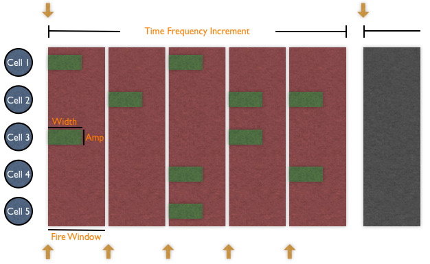
The Time Increment is divided into Fire Windows which last 0.0025 seconds.
Each cell throws a new random number at the start of a Fire Window and compares the
number thrown with the converted data. Any cell with a random number less than the converted
data gets to integrate the stimulus. This integration lasts for Width seconds as input by
the user.
For example, an Input stimulus receives the number 0.5 on its port which is then converted to
a probability of 0.125 that a cell will integrate the stimulus at the start of a Fire Window.
Cell 1 throws the random number 0.034, so it gets to integrate the stimulus,
but Cell 2 throws 0.784 so it does not.
Converting Data to Probabilities
There are two major influences to the probability of firing, Dynamic Range and data read from the file/port.
Dynamic Range
In the input file, the user specifies a Dynamic Range for integrating stimulus. In a given second,
a cell would be expected to integrate the stimulus at least at the minimum rate, but no greater
than the maximum rate.
For example, if the Dynamic Range was given as from 20 Hz to 80 Hz, then a cell should integrate the
stimulus at least 20 times in one second, but no more than 80 times in one second.
So, if the only time a cell has the option to integrate is at the beginning of the Fire Window, and a
Fire Window last 0.0025 seconds, then a cell will integrate with probability equal to 0.0025 times
the current value from the dynamic range (i.e between 20 and 80 Hz). That current value is chosen based on the data.
Data Read
In order to determine whether the cell should use the minimum Dynamic range, the maximum Dynamic range, or
somewhere in between, the data is examined. In the case of file based stimulus, the entire file is read in and
the maximum and minimum data value are discovered. These extrema allow every individual data value to be scaled to a
number from 0 to 1. This scaled value then corresponse to some percentage of the dynamic range to use. That is,
0 means that the minimum range should be used, 1 means the maximum range should be used, while 0.5 would mean to
use a range in the middle.
For input stimulus, there is no way for NCS to know what the largest and smallest values would be, so it assumes
that it will read an already scaled value (0-1) off the port, then select the daynamic range from that.
Integrating Stimulus
Once the data has been converted and the approiate dynamic range selected. The probability is calculated and
each cell throws a random number. Cells with random numbers less than the computed probability get to integrate
the stimulus. These cells will now use the AMP_START and WIDTH properties of the stimulus.
Amplitude
When the stimulus is integrated, the value contained in AMP_START is sent to the cell. The stimulus can be set
to either of two modes: CURRENT or VOLTAGE.
CURRENT
The amp specified is added to electrical current from other sources (Channels, Adjacent compartments, etc.)
so that the sum of all currents can be use to affect the cell's membrane voltage.
VOLTAGE
The amp specified bypasses all other electrical current and sets the cell's membrane voltage to the same
number (i.e. The stimulus is treated as a voltage value and not as an electrical current that must be
mathematically transformed into a voltage)
Width
The stimulus will be applied for a certain number of timesteps before it shuts down and waits for the next Fire
Window. The user will specify how many seconds this Width should be.
Customizing Stimulus Further
The example given so far have shown only one value being read from the file or read off the port in order to
determine if a cell will fire. Using FREQ_COLS and CELLS_PER_FREQ, more values can be sent to NCS to add more
variance to the firing rate.
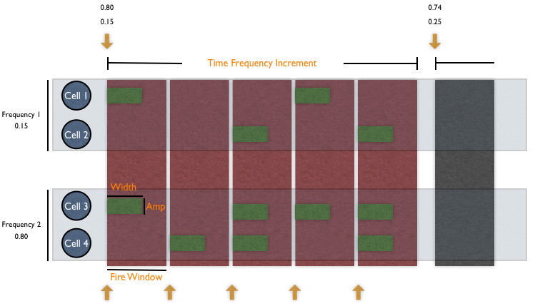
Frequency Columns
This just means how many different values (frequencies) will be read in at the start of the Time Increment.
For example, an Input stimulus can declare three FREQ_COLS and send 0.12, 0.78, 0.43. Some cells will
use the first value to establish a probability of integration, while other cells will use the second value.
And a third group of cells will use the final value.
Cells Per Frequency
This determines how many cells are assigned to each frequency. Since there is only one number in CELLS_PER_FREQ
all frequencies will have an equal number (so a single frequency can't have 10 cells while another frequency has
only 5). If there are not enough cells to split between the frequencies, that is an error. If there are cells
left over after dividing them among the frequencies, those cells will not be included.
Example: There are 20 cells and 3 frequencies. If the user wants 7 cells per frequency, that is an error since
there need to be 21 cells (3*7=21). If the user wants 5 cells per frequency, then only 15 cells are assigned to
a frequency while the 5 left over cells will not be included in stimulus integrartion.
Chapter 15:
Data about cells is gathered and written to report files. Various types of data can be requested such as Voltage reports, Channel reports, etc.
| Keyword | Value | Description |
| REPORT | | Indicates the start of a report definition section |
| TYPE | | The name which is used to refer to this object |
| CELLS | | Column | (string) | | Layer | (string) | | CellType | (string) | | Compartment | (string) |
| The source of the report |
| PROB | | The probability that a qualified cell will be included in the reporting. If probability is less than 100%, then cells are chosen randomly. For Eg.: If a cell group has 80 cells at 91% reporting probability, then 73 cells would be reported on. (Actually 72.8 cells, but rounding is done to the nearest integer). |
| FREQUENCY | | The rate at which reports will be generated. For example, a one (1) indicates that a report should be produced every time step. A two (2) indicates that a report should be generated every other time step. The total number of timesteps reported will be 1/interval. |
| REPORT_ON | | The type of report to be run. (ex. VOLTAGE) |
| CHANNEL | | Replaces old channel report. By giving the name of a channel owned by the target compartment,
the values are reported in the same pattern as the old Channel Reports (see below). This differs
from the old report in that the channel family is determined during runtime, and it does not just report on the first
instance of that family. Before, if there were multiple channels of the same family, the first one defined would
always be reported. It is not necessary to use the REPORT_ON keyword for this report |
| SYNAPSE | | New USE report. By giving the type of a synapse owned by the target compartment, the USE values are reported. It is not necessary to use the REPORT_ON keyword for this report. See the Report Types section for more information. |
| SYNAPSE_RSE | | New RSE report. By giving the type of a synapse owned by the target compartment, the Redistribution of Synaptic Efficacy (RSE) values are reported. It is not necessary to use the REPORT_ON keyword for this report. See the Report Types section for more information. |
| SYNAPSE_UF | | New USE facilitation report. By giving the type of a synapse owned by the target compartment, the temporary USE value as a result of facilitation will be reported. It is not necessary to use the REPORT_ON keyword for this report. See the Report Types section for more information. |
| SYN_AUGMENTATION | | New SA report. By giving the type of a synapse owned by the target compartment, the Synaptic Augmentation (SA) values are reported. These value are actually the augmentation amount minus 1.0 because NCS requires the augmentation be at least 1.0. During the simulation, NCS will work with the augmentation amount greater than 1.0. For example, if the augmentation is 1.3, NCS will be using 0.3 in any formulas, and send 0.3 to the report. It is not necessary to use the REPORT_ON keyword for this report. See the Report Types section for more information. |
| ASCII | | Indicates that the report file should have its information written in ascii format. If this option is not included, the files will instead be written in binary format. The field after the ASCII keyword can usually be left blank, but if the optional word 'EXP' is included, the outputted values will use scientifc notation. This is useful for reports with very small values that would normally be truncated by the limit of four characters placed after a decimal point. |
| FILENAME | | The report will be written to the filename specified |
| TIME_START | | The times at which this reporting should begin. There can be multiple start times |
| TIME_END | | The times at which reporting should stop. There can be multiple stop times. |
| END_REPORT | | Indicates the end of a report definition section |
Example
REPORT
	TYPE			ASSC1_Lay4_Exc-cNAC_1
	CELLS			ASSC1	Lay4	Inh-cNAC	s1
	PROB			1
	REPORT_ON		VOLTAGE
	ASCII
	FILENAME		ASSC1_Lay4_Inh-cNAC_1.out
	FREQUENCY		1
	TIME_START		0
	TIME_END		1.8
END_REPORT
Fire Count Report Example
REPORT
	TYPE			R1_AI1_E1_FireCount
	CELLS			R1_AI_1 layer_AI E1 sE1
	PROB			1
	REPORT_ON		FIRE_COUNT
	FILENAME		R1_E1_FireCount.txt
	ASCII
	FREQUENCY		1
	TIME_START		0
	TIME_END		60
END_REPORT
Synapse USE Report Example
REPORT
	TYPE			R2A_AI1_E1_SynUSE
	CELLS			R2A_AI_1 layer_R2 E1 sE1
	# Probability of No. of cells being selected = 10%
	PROB			0.1
	REPORT_ON		SYNAPSE_USE
	SYNAPSE			ExcitSyn1_Intra_E1
	FILENAME		R2A_E1_SynUSE.txt
	ASCII
	FREQUENCY		1
	TIME_START		0
	TIME_END		60
END_REPORT
Report Types
| Keyword | Value | Description |
| VOLTAGE | | The voltage of a compartment's membrane |
| NET_CURRENT | | The net current of the compartment |
| STIM_CURRENT | | The total stimulus current of the compartment |
| SYN_CURRENT | | The total synapse current of the compartment |
| LEAK_CURRENT | | the current leak of the compartment |
| ADJ_CURRENT | | The total adjacent compartment current of the compartment |
| CHANNEL_CURRENT | | The total channel current of the compartment |
| FIRE_COUNT | | Count of all cells in a timestep that have reached the peak of a spike |
| CHANNEL_KM | | Km Channels produce (5) values
- affect of activation particle (m): m^mPower
- activation particle (m): base value
- m-infinity (m_oo)
- t_m
- The channel current (I)
This Report has been deprecated. Use CHANNEL_RPT instead. |
| CHANNEL_KA | | Ka Channels produce eight (8) values
- affect of activation (m) and inactivation (h) particles: m^mPower * h^hPower
- activation particle (m): base value
- m-infinity (m_oo)
- t_m
- inactivation particle (h): base value
- h-infinity (h_oo)
- t_h
- The channel current (I)
This Report has been deprecated. Use CHANNEL_RPT instead |
| CHANNEL_KAHP | | Kahp Channels produce seven (7) values
- affect of activation particle (m): m^mPower
- activation particle (m): base value
- m-infinity (m_oo)
- t_m
- Calcium Internal
- funct_m
- The channel current (I)
This Report has been deprecated. Use CHANNEL_RPT instead
|
| SYNAPSE_USE | | The value of a synapse's USE at the reporting timestep.
Must use SYNAPSE keyword and specifying the synapse type desired. This will report on every synapse matching that type. Note that this may report on synapses that come from multiple sources if the synapse type is used in multiple connect statements. As with other reports, each line is one time step. The synapses belonging to each compartment stay together, but there may be a variable number. For example, compartment 0 may have 2 synapses, compartment 1 may have 3, compartment 2 may have 0, etc.
The Utilization of Synaptic Efficacy of a syanpse. USE represents long-term learning in a compartment. A higher USE value results in the release of more neurotransmitters, thereby amplifying a signal whereas a lower USE value results in the release of less neurotransmitters, thereby dampening a signal.
|
| SYNAPSE_RSE | | The value of a synapse's RSE value at the reporting timestep.
Must use SYNAPSE_RSE keyword with the name of a synapse type defined. This will report on every synapse matching that type. Note that this may report on synapses that come from multiple sources if the synapse type is used in multiple connect statements. As with other reports, each line is one time step. The synapses belonging to each compartment stay together, but there may be a variable number. For example, compartment 0 may have 2 synapses, compartment 1 may have 3, compartment 2 may have 0, etc.
|
| SYNAPSE_UF | | The value of a synapse's temporarily modified USE value as a result of facilitation.
Must use SYNAPSE_UF keyword with the name of a synapse type defined. This will report on every synapse matching that type. Note that this may report on synapses that come from multiple sources if the synapse type is used in multiple connect statements. As with other reports, each line is one time step. The synapses belonging to each compartment stay together, but there may be a variable number. For example, compartment 0 may have 2 synapses, compartment 1 may have 3, compartment 2 may have 0, etc.
|
| SYNAPSE_SA | | The value of a synapse's Augmentation value. Note: The value reported is one less than the actual value. This is because during a simulation, the augmentation must be at least 1, so only the remaining amount is used in formulas. Example, if the augmentation is 1.3, on 0.3 will be reported.
Must use SYN_AUGMENTATION keyword with the name of a synapse type defined. This will report on every synapse matching that type. Note that this may report on synapses that come from multiple sources if the synapse type is used in multiple connect statements. As with other reports, each line is one time step. The synapses belonging to each compartment stay together, but there may be a variable number. For example, compartment 0 may have 2 synapses, compartment 1 may have 3, compartment 2 may have 0, etc.
|
| CHANNEL_RPT | | Replaces old channel reports. The final report's layout will be the same as the old corresponding family report (KM, KA, KAHP). The family is determined during runtime.
Must include CHANNEL keyword with name of a channel type defined.
|
Report File Formats
1. Voltage Report
Report Keyword: VOLTAGE
Sample:
0 -60.0000 -60.0000 -60.0000 -60.0000 -60.0000 -60.0000 -60.0000 -60.0000 -60.0000 -60.0000
1 -61.3750 -61.3750 -61.3750 -61.3750 -61.3750 -61.3750 -61.3750 -61.3750 -61.3750 -61.3750
2 -62.6876 -62.6876 -62.6876 -62.6876 -62.6876 -62.6876 -62.6876 -62.6876 -62.6876 -62.6876
.. ...
.. ...
Description: First column represents simulation time tick. Remaining columns are membrane voltages of a neuron (cell) for corresponding time tick.
2. Fire Count Report
Report Keyword: FIRE_COUNT
Sample:
0 0
1 5
2 12
.. ..
.. ..
Description: First column represents simulation time tick. Second column gives a count of cells that fired at corresponding time tick.
3. Synapse USE Report
Report Keyword: SYNAPSE_USE
Sample:
-1 0.0000 0.0000 0.0000 0.0000 0.0000 0.0000 0.0000 0.0000 0.0000 0.0000
0 0.5000 0.5000 0.5000 0.5000 0.5000 0.5000 0.5000 0.5000 0.5000 0.5000
1 0.5000 0.5000 0.5000 0.5000 0.5000 0.5000 0.5000 0.5000 0.5000 0.5000
.. ..
.. ..
Description: First row is a kind of header row which gives index of the post-synaptic cell. The very first value, -1, is just a place holder and can be ignored.
Actual synapse USE values are present from second row onwards. First column (second row onwards) represents simulation time tick. Remaining columns give corresponding synapse USE value for each cell index in first header row.
Chapter 16:
This section allows us to change a synapse's USE value. Effect of updated USE values can be seen on a post-synaptic cell group by using appropriate reports. Define multiple EVENT sections to change USE values many times over the course of simulation.
Sample File format for USE file to be uploaded:
0 0 0 1 1 2 ...
.25 .19 .30 .25 .25 .40 ...
First row represents the post-synaptic cell index and second row specifies corresponding synapse USE value. This is similar to the format of SYNAPSE_USE report type.
Note: The header can also be copied from a USE report file (of any duration, with any intial USE values).
| Keyword | Value | Description |
| EVENT | | Indicates the start of a Event definition section. |
| TYPE | | The name which is used to refer to this Event object. |
| USE_OVERRIDE | | Name indicates the file name which has the Synapse USE values to be loaded. Value is simulation time (in seconds) at which to load the Synapse USE values from file. |
| CELLS | | Column | (string) | | Layer | (string) | | CellType | (string) | | Compartment | (string) |
| This indicates the post-synaptic cell group associated with the synapse under consideration. |
| SYNAPSE | | Name of the synapse whose USE values will be replaced by values loaded from file. |
| END_EVENT | | Indicates the end of a Event definition section. |
Example
EVENT
	TYPE		override
	# Loading Synapse USE values at time instant 0.5 seconds during simulation.
	USE_OVERRIDE	./input/EE1USE075.txt	0.500
	CELLS		RAIN_miniColumn	layer23	E1	somaE
	SYNAPSE	synEE
END_EVENT
Contents
Next: The Brain
Last updated Wednesday 6/27/2007