Fuzzy Logic Control in a Line
Following Robot
Robert F. Reuss
Tsai-Ming Lee
Computer Science
791j: Fuzzy Systems, Spring 2001
Professor Carl Looney
May 15, 2001
Introduction
The goal of having robots do
every day tasks has long been a dream of engineers. The first widely available
robot for educational use was from HeathKit in the 1970s. Since the development
of HeathKit's robot, several educational robots have been develop, including
the one used in this project, the RCX 1.0 brick a part of the LEGO®
MINDSTORMSTM Robotics Invention SystemTM 1.5. The
RCX is based on the Programmable Brick developed at MIT Media Laboratory. The
RCX is the commercial version of the MIT's Programmable Brick.
The
RCX is the "brains" of the MINDSTORMSTM system.
It is based on a Hitachi H8 microprocessor. The H8 is an 8 bit CPU that has in
addition to the usual CPU components, serial I/O, an analog to digital converter,
and several built-in timers. The system's firmware contains the code necessary
to monitor the three sensor input ports and control the three motor output
ports. It has 6 K of user memory, provides space for 32 global and 16 local
variables, all of which are 16 bit signed integers. Three are no floating point
variables available.
To
allow better modeling of real world nonlinear problems more effectively, in the
1960s Lofti Zadeh, a graduate student at Columbia University, started the
development of fuzzy logic [5]. Fuzzy logic is exemplified by the use of
linguistic variables to represent part of the range a ordinary crisp variable
may assume. For example, a variable s, that represents speed, may vary from 0
to 100 mph. A linguistic variable, LOW may be used to represent speeds from 0
to 25 mph while other linguistic variables represent the higher ranges.
By
the 1980s fuzzy logic was being used to control simple systems. Today fuzzy
logic has expanded to include fuzzy rule based systems, fuzzy mathematics, and
the fuzzy fusion of information. These advance techniques allow the control of
complex systems.
The
concept of controlling robots by using fuzzy systems in a natural one. In this
project, two LEGO MINDSTORMSTM robots were built around the RCX 1.0 brick, then
various software control programs were downloaded into the robots. A binary
logic control program, along with three fuzzy logic control programs were
written for the project. The control programs were evaluated on a test table
consisting of a black background and white tape.
Background
The goal of this project is
to control a robot with fuzzy systems. We were trying to find out a way to
design fuzzy classifier networks, but it is limited by lack of input data such
as features. Thus, we could not train and adjust weights to classify. However,
the network architecture could work on this project. Besides, several journals
from IEEE international conference on Fuzzy System to help us fine tune our
rules and define fuzzy set
member functions. In
addition, we did compare differences between fuzzy control and binary control.
Our
fuzzy system is to control a robot to follow a white line which is attached to
the black background. The reason is to make the boundary clear and when sensor
approaches it, the input value will be a gradient. The robot was tested on
different lines such as straight lines, curve lines, crossroads, and so on.
Methodology
Robot
Building
The robots are loosely based
on the tankbot in Baum's book [1]. The basic tankbot was modified with the sensor
assembly placed on the front end and the touch button on top as shown in Figure
1.
|
|
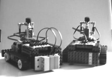
Figure 1. The robots in this
project. Note only binbot has light sensors shown because only two light
sensors were available for the project.
The
tankbot design was chosen because it is a durable design and the two track
design simplified the robot by negating the need for a steering mechanism.
Table I contains the parts list for the robots.
|
Table
I. Parts list for the project's robots |
|||
|
|
|
|
|
|
Chassis
Assembly |
Light
Sensor Assembly |
||
|
4 |
#16 beams |
2 |
Active light sensors with
medium electric connectors |
|
3 |
#4 beams |
4 |
#10 beams |
|
8 |
2x8 Technic plates |
4 |
#3 friction pegs |
|
1 |
1x8 Technic plates |
2 |
2x2 right angle Technic plates |
|
4 |
#3 friction pegs |
4 |
2x4 plates |
|
2 |
#2 friction pegs |
1 |
1x4 plate |
|
|
|
|
|
|
Motor /
Drive Train Assembly |
|
|
|
|
4 |
#8 axles |
6 |
#6 beams |
|
12 |
bushings |
8 |
#4 beams |
|
4 |
track hubs |
4 |
#6 1/5 beams |
|
2 |
tracks |
4 |
#2 friction pegs |
|
2 |
24 tooth gears |
8 |
#1.5 pegs |
|
4 |
16 tooth gears |
|
|
|
2 |
2x2 plates |
User
Button Assembly |
|
|
2 |
1x8 plates |
1 |
touch sensor |
|
2 |
1x4 plates |
1 |
short electric connectors |
|
2 |
1x2 plates |
2 |
1x2 axle bricks |
|
1 |
2x6 triangle plate |
2 |
out-axle to 90˚ in axles |
|
1 |
2x6 plate |
2 |
in-axle to 90˚ in axles |
|
2 |
motors |
1 |
#6 axle |
|
2 |
short electric connectors |
3 |
#4 axles |
|
|
|
2 |
bushings |
|
Rear
Bumper Assembly |
1 |
roll and axle short |
|
|
2 |
#16 beams |
1 |
roll and axle long |
|
2 |
#2 friction pegs |
1 |
round 2x2 brick |
|
2 |
#2 beams |
1 |
round 2x2 cap |
|
2 |
motor mounts |
|
|
|
|
|
Id Plate
Assembly |
|
|
Computer
Assembly |
2 |
2x4 Technic colored plates |
|
|
1 |
RCX 1.0 brick |
|
|
|
4 |
#1.5 pegs |
|
|
|
2 |
#6 beams |
|
|
The
output from the twin light sensors are converted to values ranging from 0 to
1023 by the on board analog to digital converter. Also the firmware can convert
the raw values to a percentage value. These light sensors are standard LEGO® parts
(#9758).
binbot
binbot is a robot that uses a binary logic control program
(Code Listing 1). It consist of three functions and main. main takes care of seeding the random number generator,
setting up the light sensors, and implementing event monitoring for the touch
sensor. It calls calibrate which determines left and right sensor values over
the black background and the white tape. calibrate then
determines lower and upper thresholds for the left and right sensors
binbot uses two thresholds rather than one for each sensor so
that when values are hovering around the threshold, it will not keep changing
the decision whether it is over the line or background (Figure 2).
|
|
|
Figure 2. The threshold idea that
binbot uses. |
After
waiting to be placed over a line (button pressed), main turns on monitoring and
calls followLine. followLine after determining whether
binbot is on the line to the left of the line, to the right
of the line, or completely off the line will either go straight, turn right,
turn left, or call findLine respectively (Table II).
|
Table
II. binbot's binary logic |
||
|
|
|
|
|
|
Right-low |
right-high |
|
left-low |
off the line, lost |
on left edge, turn right |
|
left-high |
on right edge, turn left |
go straight |
The
last function is findLine which finds the line by randomly choosing to spiral
around either to the left or to the right. Once the line is found, control
returns to followLIne. The user stops the robot by pressing the button which
main is monitoring. main shuts off both
motors and play a sound series.
fuzbot
fuzbot (Code Listing 2) used fuzzy logic with FSMF shown in Figure
3 and 4. The program find the amount of difference between the goal of the line
and what the sensors are currently reading. This difference is the error that
the program must resolve in order to follow the line. It also keep track of one
previous error to calculate the rate of change in the error. This delta value
is used by the program to know weather the robot is moving closer to the line
or further away from the line. The main function after
setting some basic items up and calling calibrate, goes into
a loop calling several functions. As binbot's main did, fuzbot main also monitor the touch
sensor in order to stop. The first function that main calls is environment_data. This function reads the sensors and determines the
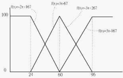
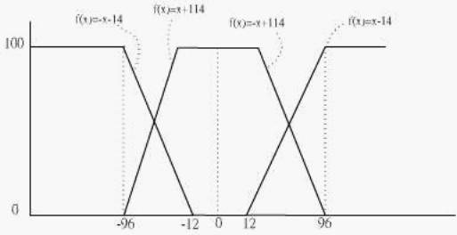
error from goal and the error delta value for the left and right sensor. Next main calls raw_to_fuzzy to convert the raw sensor data to fuzzy values
ranging from 0 to 100. Figure 3 shows the FSMF for the errors and Figure 4
shows FSMF for the deltas that the function uses in the conversion process. main calls fireRules to fire the rules the program uses.
|
|
|
Figure 3. FSMF for the left and
right errors. |
|
|
|
Figure 4. FSMF for error rate of
change, delta. |
aggregatorActionDefuzzify is called next to determine the rule with the largest
truth value that fired, then the appropriate action is perform in setting the
parameter to the motors. Table III shows the actions that the function will
take. It also converts the fuzzy motor control values to crisp values. The tweakMotor function handles the actual control of the motors.
This program also has a findLine function as did binbot. The last
function is doEdge which is like findLine except it
only spins.
|
Table
III. fuzbot's logic |
||||
|
|
Right |
|||
|
|
|
Full On (low error) |
Half On (reg error) |
Off (high error) |
|
|
Full On (low error) |
Straight Ahead |
Right controls |
Right controls (turn max) |
|
Left |
Half On (reg error) |
Left controls |
do edge |
Right controls (turn max) |
|
|
Off (high error) |
Left controls (turn max) |
Left controls (turn max) |
find line |
fuzzy1
The first version of the
fuzzy control (Code Listing 3) is designed by many rules to control robot. The
fuzzy truth of the input from two sensors will be seperated from 5 groups such
as SX_HIGH, SX_MED_HIGH, SX_MED,SX_MED_LOW,SX_LOW (X means seensor), and the
oupt from two motors has 3 groups such as Y_HIGH, Y_MED_HIGH, Y_MED_LOW, and
Y_LOW (Y means motors). Therefore, the robot could be fuzzy control by several
rules.The followign are rules for the first version.
R1.................if
(SR_HIGH) AND (SL_HIGH) then (R_HIGH),(L_HIGH)
R2.................if
(SR_MED_HIGH) AND (SL_HIGH) then
(R_HIGH),(L_MED_HIGH)
R3.................if
(SR_MED) AND (SL_HIGH) then (R_HIGH),(L_MED_LOW)
R4.................if (SR_MED_LOW)
AND (SL_HIGH) then
(R_MED_HIGH),(L_MED_LOW)
R5.................if
(SR_LOW) AND (SL_HIGH) then (R_MED_LOW),(L_LOW)
R6.................if (SR_HIGH)
AND (SL_MED_HIGH) then
(R_MED_HIGH),(L_HIGH)
R7.................if
(SR_HIGH) AND (SL_MED) then (R_MED_LOW),(L_MED_HIGH)
R8.................if
(SR_HIGH) AND (SL_MED_LOW) then
(R_MED_LOW),(L_MED_HIGH)
R9.................if
(SR_HIGH) AND (SL_LOW) then (R_LOW),(L_MED_LOW)
R10.................if (SR_MED)
AND (SL_MED_HIGH) then
(R_MED_HIGH),(L_MED_LOW)
R11.................if (SR_MED_LOW)
AND (SL_MED_HIGH) then
(R_MED_HIGH),(L_LOW)
R12.................if
(SR_LOW) AND (SL_MED_HIGH) then (R_MED_HIGH),(L_)
R13.................if
(SL_MED) AND (SR_MED_LOW) then (R_MED_HIGH),(L_LOW)
R14.................if
(SL_MED) AND (SR_LOW) then (R_HIGH),(L_LOW)
The
rule will be fire when both fuzzy truths are not 0. Then, follow the rule to
defuzzify the output to rontrol motor speed. Although the fuzzy rules control
the robot very well, we considered to built version two. The reason will be
discussed in Result/Analysis. Next section will tell the methodology for second
version.
fuzzy2
The method to control robot
with fuzzy is to use fuzzy logic control (Code Listing 4). The ideal comes from
fuzzy classifiers. It is very similar but not the same. The difference is that
there is no training to be involved because we know the weight from each rule
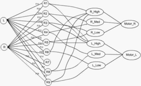
to the result and limitation of the input and output. The figure 5 shows how it works on fuzzy classifier.
L and R present inputs from two light sensors, and the symbols from R1 to R9
present each rule. Finally, right hand side symbols presents the output of the
motors. Those are difuzzified by privilous symbols such as R_high, R_med,
L_high, and so on.
|
|
|
Figure 5. Network Architecture |
We
have been tested the differences of the input values when it reads white or
black background. The value usually appears around 60 percent on white and 30
percent on black. So, it could be seperated by three group HIGH, MEDIUM, and
LOW. We define those group such as SR_High, SR_Med, and SR_Low for right sensor
input and SL_High, SL_Med, and SL_Low for left sensor input. Each group has
their own fuzzy set member function which is shown on figure 6. The horizontal
scale presents the percentage value which reading from light sensor, and the
vertical scale present fuzzy truth value. The fuzzy truth value are 0 to 100 instead of 0 to 1 because NQC
programming language does not support float. So, we expand 1 to 100 to optimize
the fuzzy truth.
|
|
|
Figure 6. FSMF |
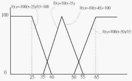
On
figure 6, each group has FSMF. define the FSMF for SL_High to F11, SL_Med to
F13, SL_Low to F15, SR_High to F21, SR_Med to F23, and SR_Low to F25. Besides,
each group have two FSMF depend on the input value. For example, if x is input
value, and f(x) is fuzzy truth, SR_High group has FSMF f(x)=100*(x-50)/15 when 50<x<65
and f(x)=100 when x>65. When each time reads the input L and R, they can
find the fuzzy truth value for each group. Those values will feed into every
rules to find out whether could fire the rules. The following are all rules.
R1...........if (SR_High) AND
(SL_High) Then (R_High),(L_High)
R2...........if (SR_High) AND
(SL_Med) Then (R_Med),(L_High)
R3...........if (SR_High) AND
(SL_Low) Then (R_Low),(L_High)
R4...........if (SR_Med) AND
(SL_Med) Then (R_Med),(L_Med)
R5...........if (SR_Med) AND
(SL_Low) Then (R_Low),(L_High)
R6...........if (SR_Low) AND
(SL_Med) Then (R_High),(L_Low)
R7...........if (SR_Low) AND
(SL_Low) Then findline();
R8...........if (SR_Med) AND
(SL_High) Then (R_High),(L_Med)
R9...........if (SR_Low) AND
(SL_High) Then (R_High),(L_Low)
For instance, if the percent
values reading from left and right sensor are 52 and 25, they feed into every
FSMF. Then, F11, ,F13, and F25 are no longer 0. So, they fire rules R6 and R9.
We take max(min(F13,F25), min(F11,F25)) and decide R6 to be the rule which we
actually take. On figure 5, R6
control motor R_Low and L_High. Thus, we could defuzzify truth value to real
value for motor. The figure7 shows how to defuzzify to real value.
|
|
|
Figure 7. Motor speed Defuzzify |
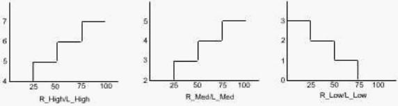
When R6 is applied, it means
right sensor is totally out of white line and left sensor is middle of white
line and black background. Then, the robot must turn left to come back white
line. Therefore, R6 control right motor to be high speed and left motor to be
low speed. Furthermore, the robot could move smoothly when it meets the curve
because it not only turn by adjusting different speed for two motor but also
slow down to prepare any situation in front of line such as sharper curve or
end of line. There is one rule without fuzzy control that is R7. It means both
sensors out of white line by incident. The situation could happen when robot
with high speed meets end or extremely sharp curve suddenly. Thus, considring difference
e between L and R to decide which way to U turn and find white line again. This
step can prevent that the robot would die when it is out of bound.
Computer Runs
The robots were evaluated on
a 24 by 40 inch tablecovered in heavy black matt photographic background paper
(Figure 8). The lines were "drawn" with 1 inch white Post-it® cover-up
tape. The light sensors are standard LEGO® parts.
Several
pattern were used for the evaluation of the software. Figure 9 shows the
patterns used. "The great curve test" evaluated the software ability
to negeociate curves with a radius of 9". The curves by necessity are made
up of short 3" pieces of tape fitted end to end. Straight bends were
tested ranging from 45˚ to 180˚. Also a tee and a cross was tested.
|
|
|
|
Figure 9 The robots were tested on various
shaped of lines. |
Results
For the 9" curve binbot passed this test, however not path wasn't very
smooth. fuzbot passed the test with a smooth path. fuzbot had the roughest path however it did complete the
test successfully.
The 90 ˚ bend gave some
trouble to binbot depending on which way he turned at the corner. fuzbot at the corner took much time to search out the line
because of his overshooting. fuzzy2 did the best and was
fairly smooth.
The 135˚ bend gave only fuzzy2 and fuzbot trouble, leaving only binbot to smoothly succeed on the line. The trouble was that
both fuzzy robots were going at a fairly high rate of speed when they came to
the corner. The result was that both fuzzy controlled robots overshoot the
corner.
The straight line gave little
trouble to any of the robots. binbot the most trouble of all the robots because
it would often get one sensor off the line causing it to verve back sharply.
The cross and the tee gave very
little information and will not be discussed further.
Analysis and Conclusions
The trouble that fuzbot had with the test was that its code was too long to
allow the loop to cycle in a short iteration. Even on the long straight lines,
it would often over shoot the line giving a very chaotic performance. Faster
CPU could eliminate much of these problems.
Often time binbot had the best performance not because of the sophistication
of its programming but because the code executes quickly allowing it to take
many sensor readings.The reason to do two version is that the first version of
the fuzzy control
have more rules. It seems to
be great. However, it is limited by output which is only 8 different speed for
each motor. If we build more rules on it, the output will be more fix. It means
that the behavior approaches binary control. For example, there have 5
different groups seperated by input such as SR_HIGH,SR_MED_HIGH, SR_MED,
SR_MED_LOW,SR_LOW, and 4 different groups in output. Each group will only have
2 different speeds which could be difuzzyfied. It can't be three because the
rules has given
them restriction. If we give
it three, ans when fuzzy control it, the robot could get wrong turn. For
instance, when sensor L belongs to SL_MED_HIGH, sensor R belongs to SR_MED, and
the fuzzy truth is low, then the speed of motor_R is 4 (R_MED_HIGH) and motor_L
is 5 (L_MED_LOW). So, it is supposed to turn left by rules, but the robot turn
to right. Therefore, we have to give only 2 speeds for each group, but the fuzzy
control approaches binary control. Thus, we decide to build second version of
fuzzy control, although the robot works similar fuzzy control.
Tasks
|
Robert F. Reuss |
Tsai-Ming Lee |
||
|
|
Report Introduction
Methodology
robot, binbot, fuzbot
Computer Runs
Results
Analysis & Conclusions Programming
binbot (binary logic robot) fuzbot (fuzzy logic robot) Computer Runs
"The great curve test" |
|
Report Background
Methodology
fuzzy1, fuzzy 2
Results
Analysis & Conclusions Programming
fuzzy1 (fuzzy logic robot)
fuzzy2 (fuzzy logic robot) Computer Run
Straight bend test |
References
[1] Dave Baum, Dave Baum's Definitive Guide to LEGO® MINDSTORMSTM ,
Emmeryville,
California: APress, 2000.
[2] Bing-Yang Chee, Sherman Y.
T. Lang, and Peter W. T. Tse, "Fuzzy Mobile Robot
Navigation
and Sensor Integration," 1996 IEEE
International Conference on Fuzzy Systems, Vol. 1, pp. 7-12, Sep. 1996.
[3] J.-S. R. Jang, C.-T. Sun,
and E. Mizutani, Neuro-Fuzzy and Soft
Computing,
Upper
Saddle River, New Jersey: Prentice Hall, 1997.
[4] Sng Hong Lian, "Fuzzy
Logic Control of an Obstacle Avoidance Robot," 1996
IEEE International Conference on Fuzzy
Systems, Vol. 1, pp. 26-30, Sep.
1996.
[5] Carl Looney, Class Notes
for CS791j, Reno Nevada: University of Nevada at
Reno,
2001.
[6] Witold Pedrycz, Fuzzy Sets Engineering, Boco Roton,
Florida: CRC Press, Inc.,
1995.
[7] Hartmut Surmann, Jorg
Huser, and Liliane Peters, "A Fuzzy System for Indoor
Mobile
Robot Navigation," IEEE
Internationsl Conference Fuzzy Systems, Vol. 1, pp. 83-88, March 1995.
[8] Kauzuo TANAKA,
"Model-based Fuzzy Control of a Trailer Type Mobile Robot,"
IEEE Internationsl Conference Fuzzy
Systems, Vol. 1, pp. 65-70, March
1995.